Today we are going to setup a wireless point to point network using 2 LigoWave DLB 5-20ac radios. This will allow you to extend your network beyond the maximum distance of wired connections. Let’s get these unboxed, configured and installed so we can test the bandwidth with some security cameras. This post should provide you with all the information you need to get up and running with LigoWave radios. By the way, this is not anad for LigoWave.
So basically, what I have here is 2 radio antennas. When they are pointed towards each other they act as a super long network cable allowing you to extend your network up to 15km or 9.32 miles away depending on your country’s wireless regulations. So no need to spend hours and lots of money installing special underground cables and conduit. These devices are from LigoWave and can be used pretty much anywhere you need to extend your home or corporate network, where you have line-of-site and of course a power source at each end. This could be between 2 skyscrapers, 2 office buildings, 2 small commercial structures, constructions sites, or from your house to any out-structure like a workshop, barn or shed.


LigoDLB 5-20 ac
$188.00 (as of May 16, 2024 19:11 GMT -06:00 - More infoProduct prices and availability are accurate as of the date/time indicated and are subject to change. Any price and availability information displayed on [relevant Amazon Site(s), as applicable] at the time of purchase will apply to the purchase of this product.)
![Anker Unibody Aluminum 3-Port USB 3.0 and Gigabit Ethernet Hub with 1.3ft / 40cm USB 3.0 Cable [Ethernet Port RTL8153 Chipset + USB Ports VL812 Chipset] #1](https://m.media-amazon.com/images/I/41z1OiSln0L._SL100_.jpg)
![Anker Unibody Aluminum 3-Port USB 3.0 and Gigabit Ethernet Hub with 1.3ft / 40cm USB 3.0 Cable [Ethernet Port RTL8153 Chipset + USB Ports VL812 Chipset] #2](https://m.media-amazon.com/images/I/51YzSrBhkeL._SL100_.jpg)
![Anker Unibody Aluminum 3-Port USB 3.0 and Gigabit Ethernet Hub with 1.3ft / 40cm USB 3.0 Cable [Ethernet Port RTL8153 Chipset + USB Ports VL812 Chipset] #3](https://m.media-amazon.com/images/I/31b3x3MJbRL._SL100_.jpg)
![Anker Unibody Aluminum 3-Port USB 3.0 and Gigabit Ethernet Hub with 1.3ft / 40cm USB 3.0 Cable [Ethernet Port RTL8153 Chipset + USB Ports VL812 Chipset] #4](https://m.media-amazon.com/images/I/31jbCXpziZL._SL100_.jpg)
![Anker Unibody Aluminum 3-Port USB 3.0 and Gigabit Ethernet Hub with 1.3ft / 40cm USB 3.0 Cable [Ethernet Port RTL8153 Chipset + USB Ports VL812 Chipset] #5](https://m.media-amazon.com/images/I/51CCkmoUeGL._SL100_.jpg)
Anker Unibody Aluminum 3-Port USB 3.0 and Gigabit Ethernet Hub with 1.3ft / 40cm USB 3.0 Cable [Ethernet Port RTL8153 Chipset + USB Ports VL812 Chipset]
The working temperatures range from -40 Celsius or Fahrenheit up to +65 Celsius or 140 Fahrenheit. Their website says this model is made to perform with Internet connectivity, video surveillance and rural connectivity in mind. We’ll test that out, especially the security camera part with my 8MP and 12MP cameras.
The model number 5-20ac indicates this radio uses the 5GHz frequency and the 20 is the gain or dBi. (Basically, this means the focus and shaping of the radio waves from the device and the higher the number the more direct or flat the waves will be.) It has a data throughput of 500Mbps but again we’ll test that out. These cost about $100 US each and if you are setting up a point-to-point network, you’re going to need 2.


Vansky Adjustable Attic Antenna Mount - Outdoor TV Antenna Mounting Pole Universal Mount Brackets - Easy Installation, Solid Structure, Weather Proof (1in Diameter Mount Pipe)
Let’s get these configured here inside before heading out to my test locations.
As indicated in the install guide, the IP address of these devices is 192.168.2.66. If I plug the radio into my switch on my network and then try to access it with Chrome using the IP address, the browser times out. If I try to ping the radio, it cannot be found. Looking at my network, my router is on the 192.168.0.x subnet and therefore can only access devices on the .0 network.
I want the radios on the same network as all my other devices including my IP security cameras, computer and my WiFi network so that they can all communicate. I want my PC in my house to record footage taken by cameras on the remote radio and I want Internet access at the remote radio end from my home modem. To update the radios’ subnet from .2 to .0, I need to be on the same .2 subnet, so let’s plug the radio’s network directly into my PC and manually change the IP address of my PC to be on the .2 subnet. I’ll use a USB hub with an ethernet port but you can use the built in ethernet port on your computer. If your computer is WiFi only, I’ll add the link for my hub in the description below because you need to be wired to the radio to switch the subnet.
Let’s unplug this radio from the PC and mark AP.66 on the back so I don’t get them mixed up when installing them. I’ll plug it into my network switch. Let’s plug in the other one into my PC and do the setup as a station accessing the AP. Let’s also make them face each other.
Here in the other radio, I’ll select my region, update the password, update its Friendly name to LigoStation67 and in this case, we’ll make the IP address fixed at 192.168.0.67. Now, on the Wireless Config page, the Operating mode will be Station (iPoll3) and I’ll drop the power. Let’s find the AP unit. Click on the SSID and let’s search for the AP. Click on it and enter the password. Hit save to confirm all the changes. Unplug the station from the PC. Now this station is separated from my PC and my network. This is a good time to change my PC’s IP address back to .0
In Chrome, let’s log into the access point. In the upper right we see there is 1 station connected. The LEDs on the back also indicate they are linked. On the Wireless Networks page, you can see the Station attached. Click on the IP address and log into the remote station. In the upper right corner, it says the signal strength is too strong, you want to be around -50. That’s because the units at too close. Maybe in the field I’ll enable the Automatic Transmit Power Control (ATPC) so the radios can control their power levels themselves.
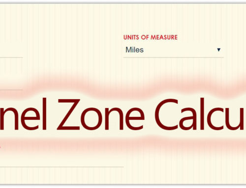
When setting up the 2 radios, keep in mind that they radio waves between each device form a stretched oval pattern. Like when you take a partially inflated balloon and stretch it. The waves are at their maximum width at the half way between the radios. That space of radio frequencies is known as the Fresnel zone.
Install your 2 radios so they have line-of-sight. Since these aren’t lasers, and use radio frequencies to communicate and the waves get shaped like this, this is the Fresnel zone. Looking at it from the radio’s point of view, it’s a circle. We need to protect that from hitting any structures or the ground in order to keep a strong signal strength without interference. Keep that in mind when deciding the height of your antennas. Watch out for things like trees or giraffes because they could disrupt your signal.
For these 5GHz radios located half a mile apart or 800m, the wave Fresnel zone’s radius is 11.39 feet or 3.5 meters. If the land is level without obstruction, you could have each radio at this height. You could also have one higher than the other, as long as the Fresnel zone is safe. But how do you know how big the Fresnel zone will be when planning the system? I’ll create a calculator to my blog where you can figure out the radio wave radius based on the frequency and radios’ distance. Enter the distance between the radios and their frequency and your radius will be displayed.

Let’s add some equipment to the station side. I will add a PoE switch to split the connection from the Station radio so multiple devices can be online at once, like these cameras and a PC. The PoE switch will also power the security cameras. Each of these cameras is on the .0 subnet and function on my network when wired in.
Auto Amazon Links: No products found.
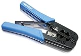


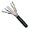
TRENDnet Crimping Tool, Crimp, Cut, And Strip Tool, For Any Ethernet or Telephone Cable, Built-In Cutter And Stripper, 8P-RJ-45 And 6P-RJ-12, RJ-11, All Steel Construction, Black, TC-CT68
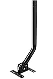
I’m still amazed that this setup was able to transfer those high quality images from such a distance. I’m working on getting some access to higher structures where I can also better align the radio and hopeful push the distance further. Hopefully I’ll be doing a video on that in the future. When I mount these permanently, I’ll be using a J-mount pole like this one here. Building a point-to-point wireless bridge is much easier than I expected and the bandwidth results were beyond my expectations. LigoWave has certainly simplified the process from the physical install right to the configuration. The configuration has a lot of advanced features which is great if you want more control over the device functionalities. Definitely a great solution to tie in another building, office, workshop or barn into your main network without having to dig trenches and running conduit to bury lines. This device can be setup in a point to multi point network and as an individual access point or hotspot; but we’ll save that for upcoming videos.
I think that’s everything you need to know to get up and running. I hope that you found this information helpful. Check out my blog for more information and LigoWave also has in depth coverage of all their products on their website (which is really well done) and lot of setup and configuration help available on their Wiki.
Worldwide distributors: https://www.ligowave.com/distributors
Fresnel Zone Calculator: https://www.hometechdiy.com/fresnel-zone-calculator/
https://www.ligowave.com/wiki/
https://www.ligowave.com/wiki/ligodlb-configuration-scenarios/

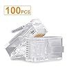
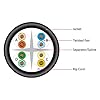
SHD RJ45 Connectors, Cat6 Connector Cat5e Connectors Cat5 Connectors RJ45 Ends Ethernet Cable Crimp Connectors-100Pcs
$8.89 ($0.09 / Count)


Cat 6 Ethernet Cable 5ft 6Pack, Outdoor&Indoor, 10Gbps Support Cat 8 Cat 7 Network, Heavy Duty Internet LAN Patch Cord, Solid High Speed Weatherproof Cable for Router, Modem, Xbox, PS4, Switch, White
$14.99